Valve Drawing Symbols
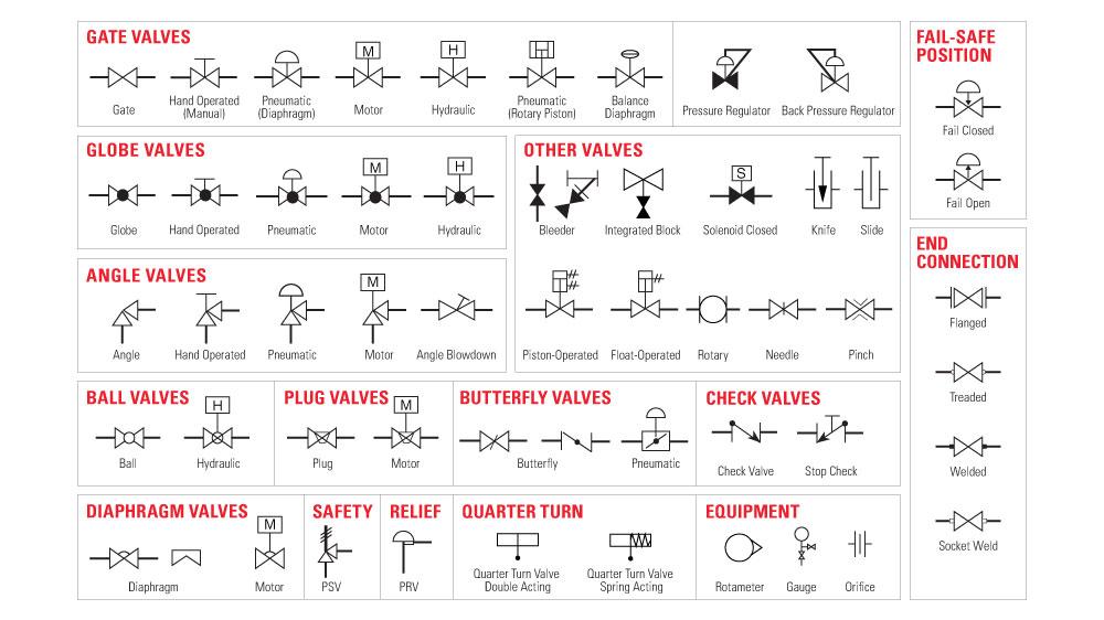
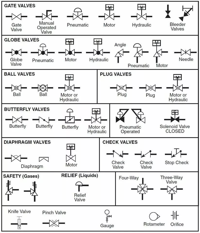
Valve Drawing Symbols - The symbol typically consists of the actual valve symbol, and the actuation method such as pneumatic, hydraulic, or electric. Valves are technically fittings, but are usually discussed as a separate category. Users can also import svg and other image files to create a custom p&id library for any situation. In such cases, information concerning the valve type may be conveyed by the component Web typical drawing symbols quick fill gas meter water meter temperature gauge pressure gauge flow switch panic button. A globe valve operates by a barrier, such as a plug, moving up or down to seal a stationary ring. Web valve symbols valves are used to control the direction, flow rate, and pressure of fluids. Web in each process and instrumentation diagram, valves have specific symbols that make them easy to recognize. These illustrations, commonly referred to as piping and instrumentation diagram (p&di) symbols, may vary slightly between organizations but similar sketches are used to identify types and position of valves. Similarly, this symbol shows a circle just as the ball valve does. Web these valve symbols convey essential information about the valve type, function, and operation, facilitating effective communication among engineers, designers, and technicians. Users can also import svg and other image files to create a custom p&id library for any situation. These illustrations, commonly referred to as piping and instrumentation diagram (p&di) symbols, may vary slightly between organizations but similar sketches are used to identify types and position of valves. A valve is a device that regulates, directs or controls the flow of a fluid (gases, liquids, fluidized solids, or slurries) by opening, closing, or partially obstructing various passageways. Such as ball valve, plug valve, refile valve, gate valve, check valve, butterfly valve. Equipment, piping, vessels, heat exchangers, pumps, instruments, and valves. They include the valve symbol with modifier and the generic valve symbols. Web • examples of the common types are the globe valve, gate valve, ball valve, plug valve, butterfly valve, diaphragm valve, check valve, pinch valve, and safety valve. Web engineers use control valve symbols to identify the type of control valve they want to specify for a given application. This comprehensive overview delves into the world of valve symbols, providing detailed explanations and examples to empower professionals with the. Web piping and instrument diagram standard symbols detailed documentation provides a standard set of shapes & symbols for documenting p&id and pfd, including standard shapes of instrument, valves, pump, heating exchanges, mixers, crushers, vessels, compressors, filters, motors and connecting shapes. Valves are used to control the direction, flow rate, and pressure of fluids. Web learn about types of valve symbols. Web piping and instrument diagram standard symbols detailed documentation provides a standard set of shapes & symbols for documenting p&id and pfd, including standard shapes of instrument, valves, pump, heating exchanges, mixers, crushers, vessels, compressors, filters, motors and connecting shapes. This comprehensive overview delves into the world of valve symbols, providing detailed explanations and examples to empower professionals with the.. Web engineers use control valve symbols to identify the type of control valve they want to specify for a given application. These illustrations, commonly referred to as piping and instrumentation diagram (p&di) symbols, may vary slightly between organizations but similar sketches are used to identify types and position of valves. Web a piping and instrumentation diagram (p&id) is a graphic. Web a piping and instrumentation diagram (p&id) is a graphic representation of a process system that includes the piping, vessels, control valves, instrumentation, and other process components and equipment in the system. We have two main types of valve symbols used in the p&id. Similarly, this symbol shows a circle just as the ball valve does. Figure 1 shows the. A valve is a device that regulates, directs or controls the flow of a fluid (gases, liquids, fluidized solids, or slurries) by opening, closing, or partially obstructing various passageways. It should be noted that globe and gate valves will often be depicted by the same valve symbol. Web valve symbols valves are used to control the direction, flow rate, and. Web in this article, we highlight some of the most common p&id valve symbols, process lines, end connections and other vital components. Web a piping and instrumentation diagram (p&id) is a graphic representation of a process system that includes the piping, vessels, control valves, instrumentation, and other process components and equipment in the system. Valves are used to control the. In this article, we will identify the most commonly used control valve symbols. Web what are valve symbols and why are they important in engineering drawings? A piping and instrumentation diagram (p&id) includes symbols for ball valves, communication lines, vessels and other components. Users can also import svg and other image files to create a custom p&id library for any. Equipment, piping, vessels, heat exchangers, pumps, instruments, and valves. Some valves are capable of throttling flow, other valve types can Web isometric drawing symbols for piping valves. With lucidchart, it's easy to access all of the featured p&id symbols. This comprehensive overview delves into the world of valve symbols, providing detailed explanations and examples to empower professionals with the. Web • examples of the common types are the globe valve, gate valve, ball valve, plug valve, butterfly valve, diaphragm valve, check valve, pinch valve, and safety valve. Equipment, piping, vessels, heat exchangers, pumps, instruments, and valves. Learn the meanings and applications of various valve symbols, enhancing communication and understanding in engineering projects. Web a piping and instrumentation diagram (p&id). Web a piping and instrumentation diagram (p&id) is a graphic representation of a process system that includes the piping, vessels, control valves, instrumentation, and other process components and equipment in the system. In such cases, information concerning the valve type may be conveyed by the component A piping and instrumentation diagram (p&id) includes symbols for ball valves, communication lines, vessels. Web engineers use control valve symbols to identify the type of control valve they want to specify for a given application. Web proficient interpretation of valve symbols enhances project efficiency, reducing errors and promoting the seamless integration of valves into complex industrial processes. Figure 1 shows the symbols that depict the major valve types. Web in this article, we highlight some of the most common p&id valve symbols, process lines, end connections and other vital components. Web here, we will focus on valve symbols, depicted typically as two lines (representing piping) connected to a boxy or triangular symbol that represents the valve’s type. The symbol typically consists of the actual valve symbol, and the actuation method such as pneumatic, hydraulic, or electric. Valve symbols are graphical representations of various types of valves used in piping and instrumentation diagrams (p&ids) and other engineering schematics. Valve symbols are used to signify the pressure, flow and direction of fluids through a valve. Web • examples of the common types are the globe valve, gate valve, ball valve, plug valve, butterfly valve, diaphragm valve, check valve, pinch valve, and safety valve. Web learn about types of valve symbols used in p&id and iso drawing. These illustrations, commonly referred to as piping and instrumentation diagram (p&di) symbols, may vary slightly between organizations but similar sketches are used to identify types and position of valves. Web these valve symbols convey essential information about the valve type, function, and operation, facilitating effective communication among engineers, designers, and technicians. It should be noted that globe and gate valves will often be depicted by the same valve symbol. Equipment, piping, vessels, heat exchangers, pumps, instruments, and valves. This comprehensive overview delves into the world of valve symbols, providing detailed explanations and examples to empower professionals with the. Figure 1 shows the symbols that depict the major valve types.
Valve Drawing Symbols
The Most Common Control Valve Symbols on a P&ID Kimray
check valve symbols on drawings Symbols engineering process diagram

Industrial Valve and Actuator Symbols Process Control Solutions Blog
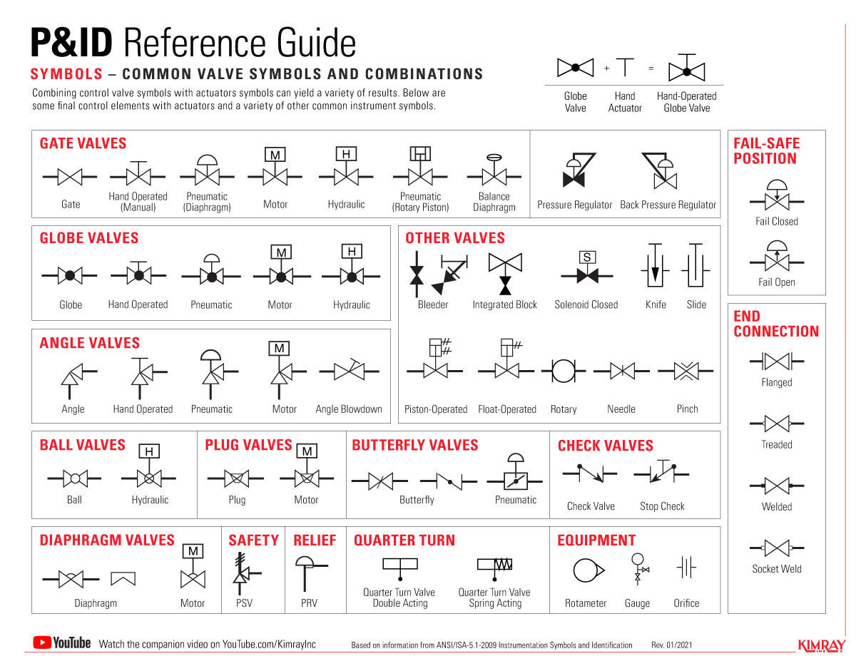
The Most Common Control Valve Symbols on a P&ID Kimray

Valves Symbols used in P&ID and Piping Isometric drawings YouTube
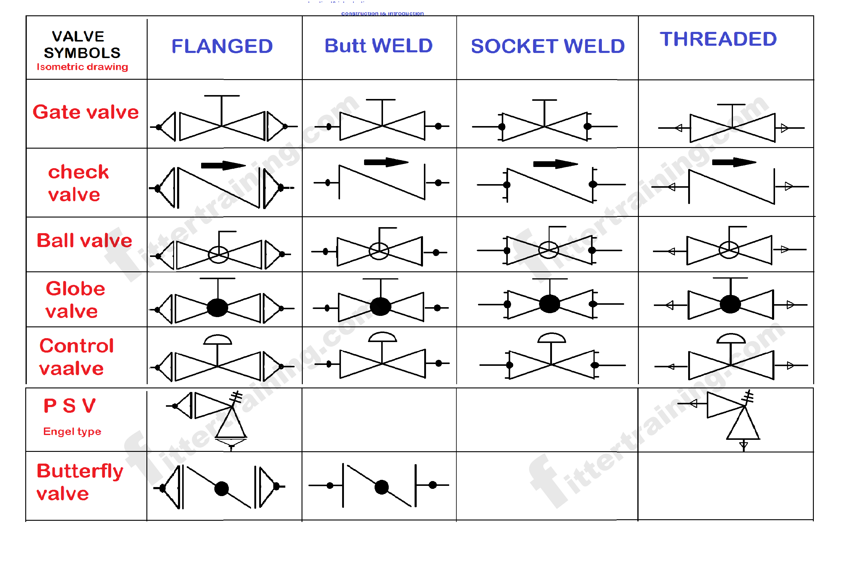
Isometric Pipe Valve Drawing Symbol

Valve Drawing Symbols

Types Of Valves, Their Functions And Symbols Engineering Discoveries
![How to Read P&ID Component & Valve Symbols [w/ Download]](https://www.geminivalve.com/wp-content/uploads/2020/07/Valve-Symbols-2-way@2x-100.jpg)
How to Read P&ID Component & Valve Symbols [w/ Download]
Web In Each Process And Instrumentation Diagram, Valves Have Specific Symbols That Make Them Easy To Recognize.
Web We've Broken Them Down Into Seven Main Groups:
Some Valves Are Capable Of Throttling Flow, Other Valve Types Can
Users Can Also Import Svg And Other Image Files To Create A Custom P&Id Library For Any Situation.
Related Post: